BIG 5十角刀片面銑刀盤 – MFPN

京瓷車刀(Kyocera)BIG 5十角刀片面銑刀盤 – MFPN

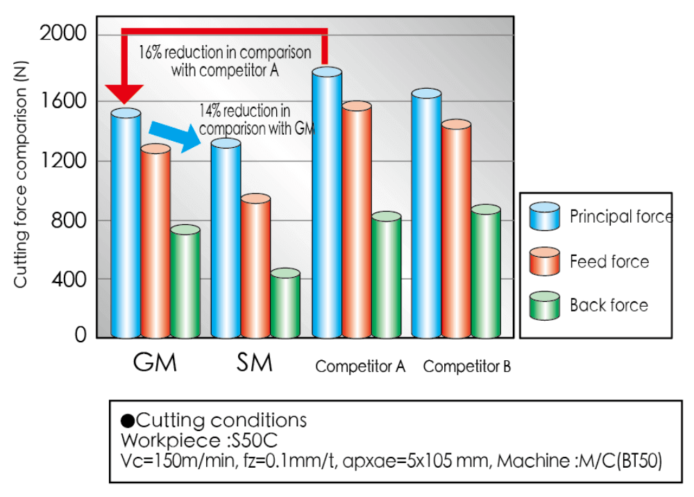
High-Efficiency Facemill

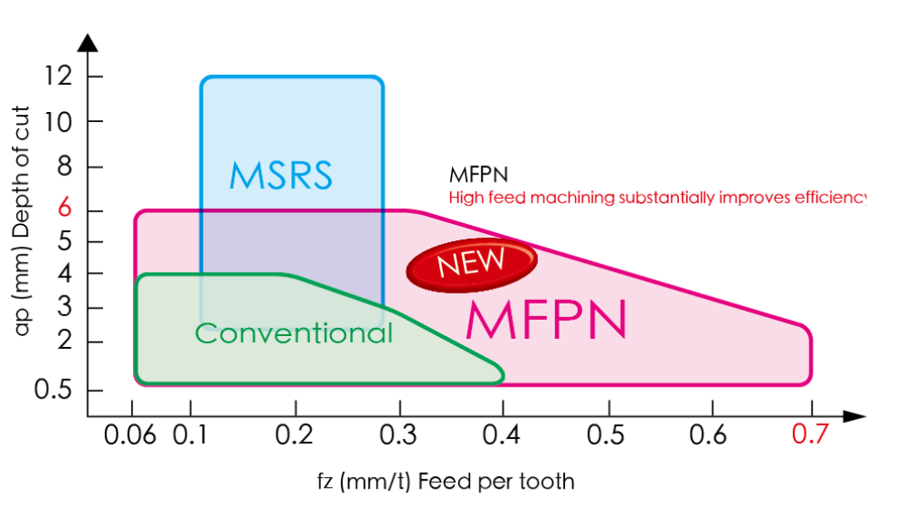
MFPN

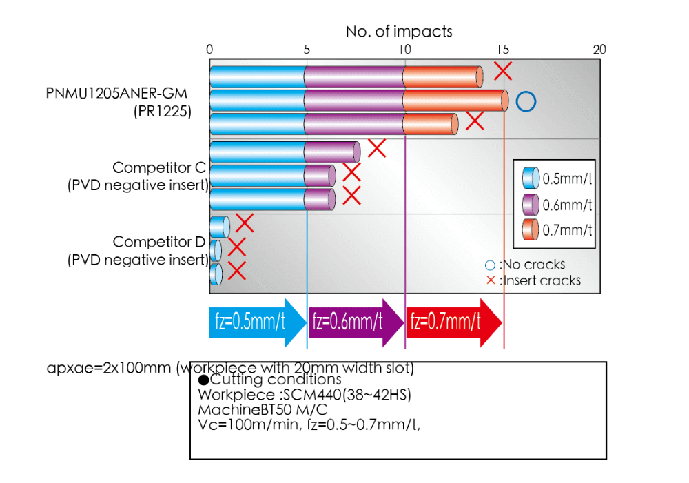
Low cutting force and excellent fracture resistance

Five Advantages of BIG Pentagon

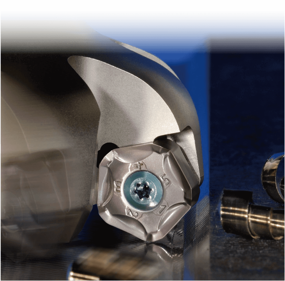
  1. Roughing and general-purpose facemill with 10-cornered pentagonal inserts
  2. Low cutting force due to helical cutting-edge design
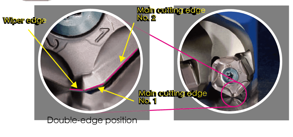
  3. Fractures suppressed by double-edge position
  4. Chip evacuation improved by 3-dimensional chipbreaker
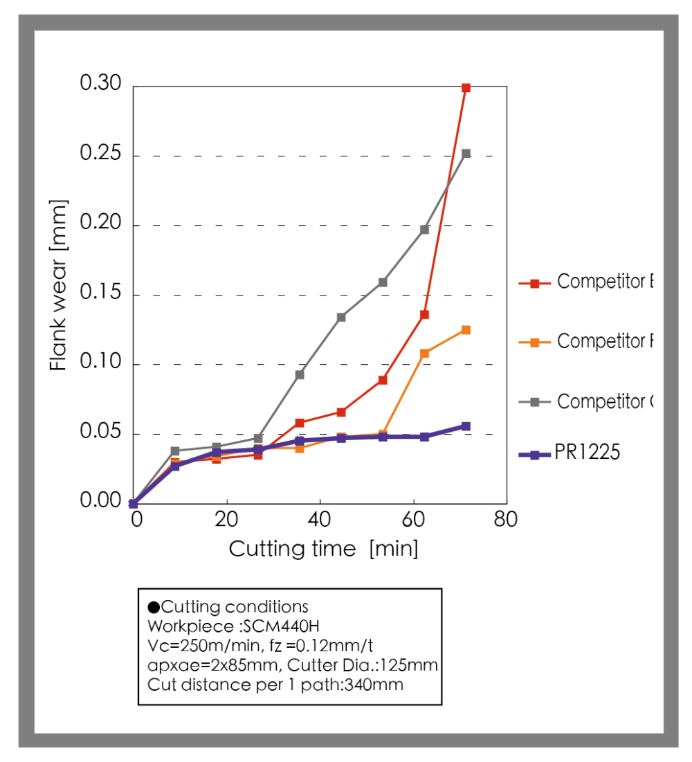
  5. Long tool life with PR12-Series MEGACOAT carbide inserts

產品介紹

  1. Roughing and general-purpose facemill with  10-cornered pentagonal inserts
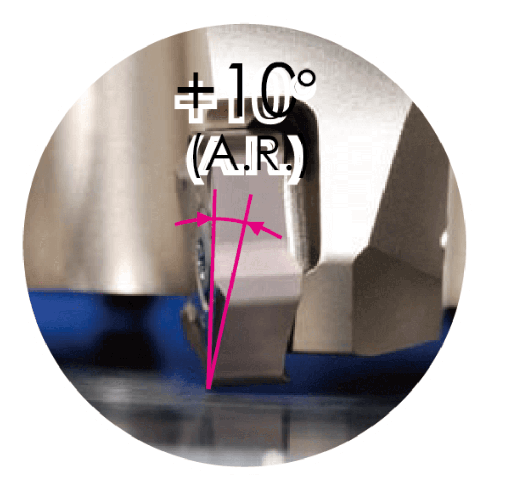
  2. Low cutting force due to helical cutting-edge design
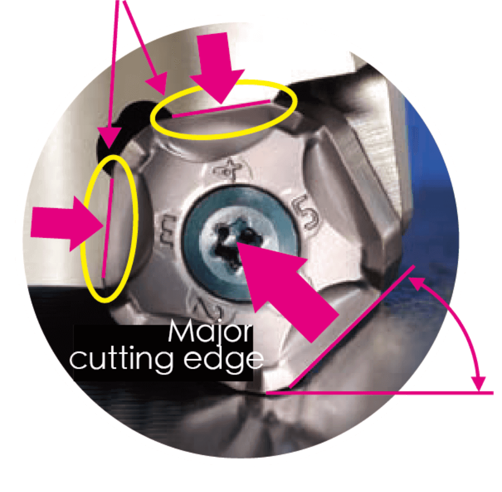
  3. Fractures suppressed with double-edge position
    Double-edge position
    Major cutting edge makes chips thin, thereby reducing impact load at entrance and exit of workpiece
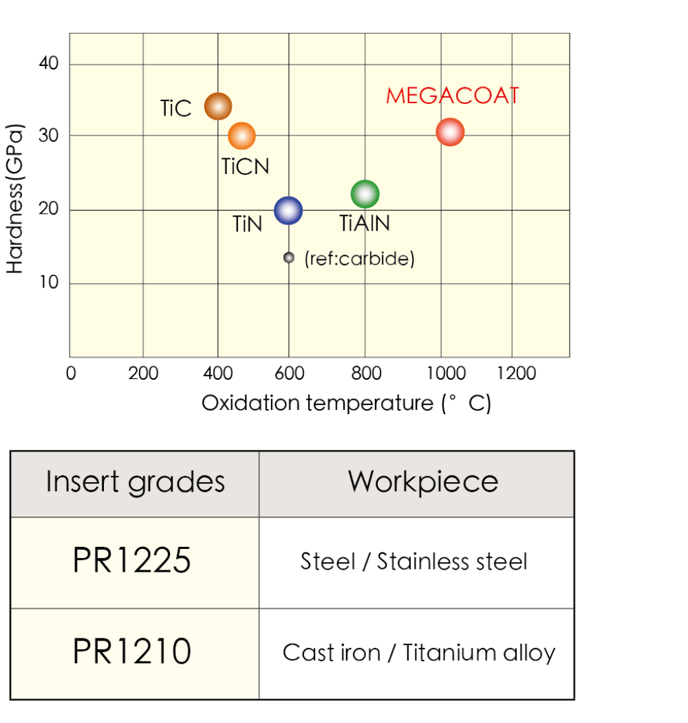
  4. Long tool life with PR12-Se Long tool life with PR12-Series MEGACOAT carbide inserts
    MEGACOAT

    Long tool life and high-speed milling due to high hardness and high oxidation resistance
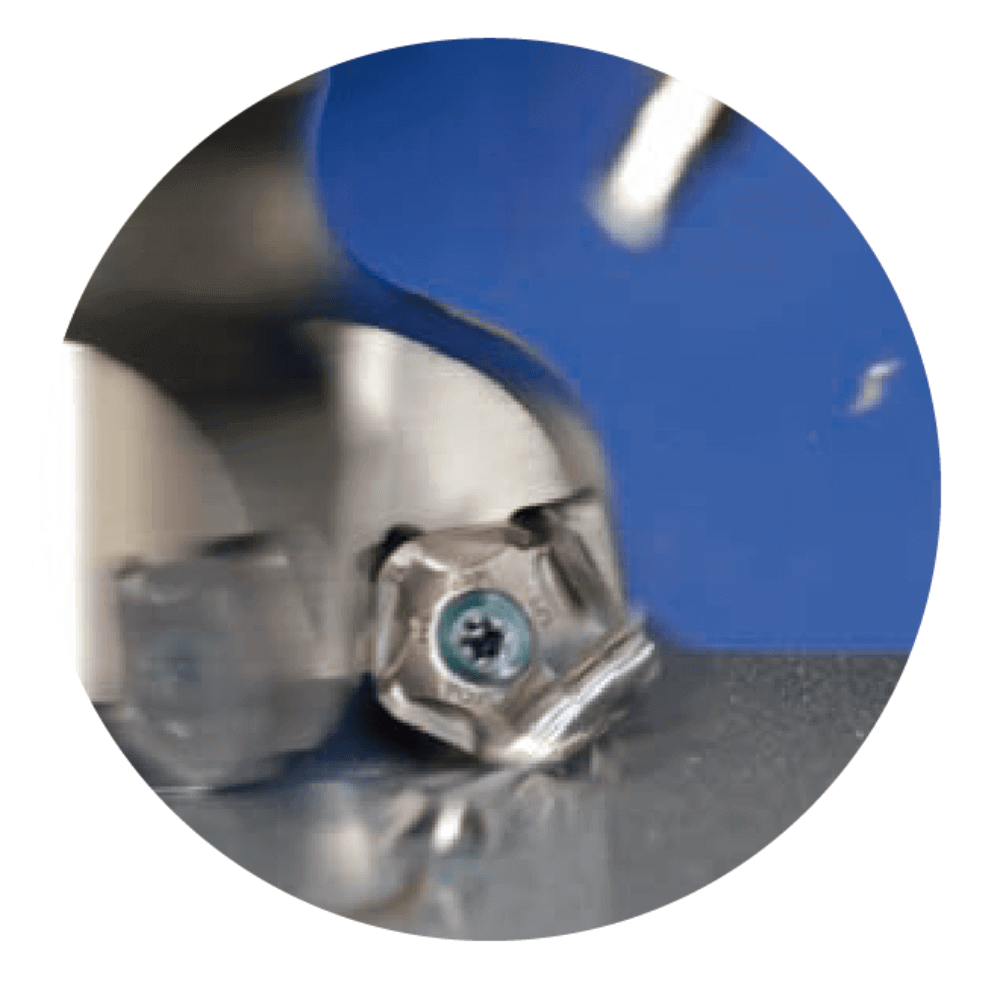
  5. 3-dimensional chipbreaker improves chip evacuation

    Smooth chip evacuation reduces chip-biting

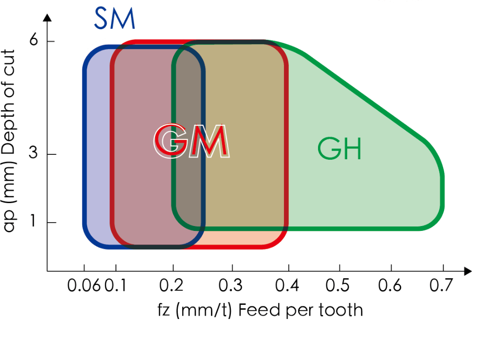
    ·3-types of chipbreakers enable coverage of a wide range of milling conditions


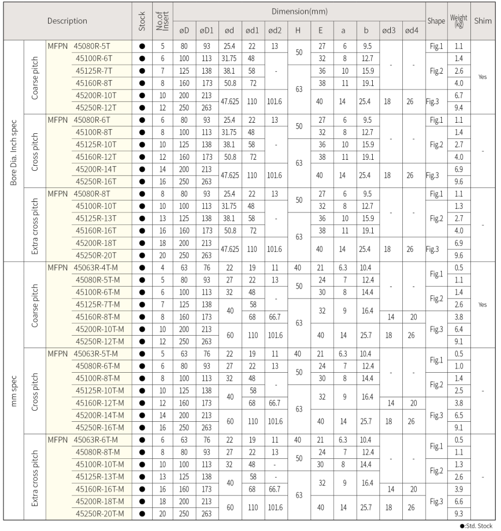
MFPN45

202 未命名 2 19 resized

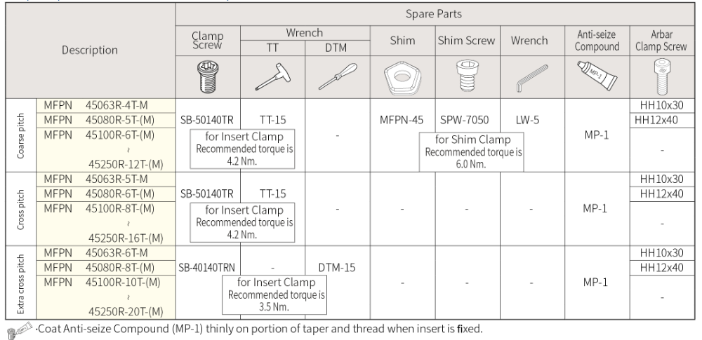
  • Spare Parts
    Spare parts (mm / inch common spec)

未命名 2 20 resized

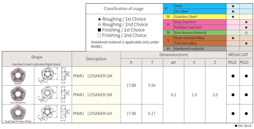
  • Insert description
    Milling Inserts (with hole)

未命名 2 21 resized

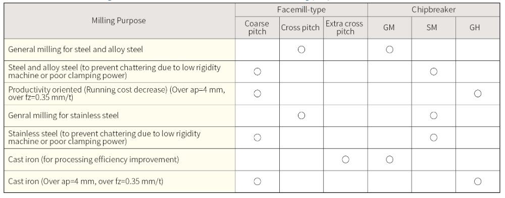
  • Reference for selecting a facemill and insert suitable for each milling purpose

未命名 2 22 resized

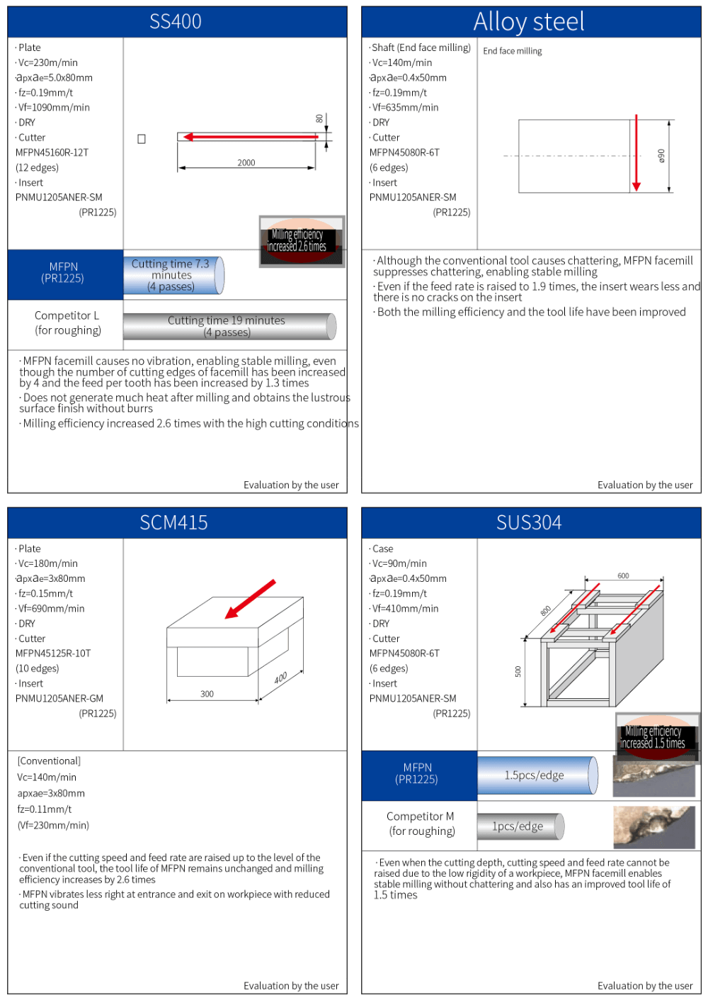
  • Case studies未命名 2 24 resized
  • Precautions for use (How to mount an insert)

    1.Be sure to remove dust and chips from the insert mounting pocket.
    2.After applying anti-seize compound on portion of taper and thead, while pressing the insert against the constraint

    surfaces, put the screw into the hole of the insert and tighten the screw with appropriate torque. See Fig. 1 and Fig. 2. Recommended tightening torque → The torque for coarse pitch and cross pitch (using M5 screw) is 4.2 Nm.

    The torque for extra cross pitch (using M4 screw) is 3.5 Nm.
    3.After tightening the screw, make sure that there is no clearance between the insert seat surface and the bearing surface of

    the holder and between the insert side surfaces and the constraint surface of the holder.
    4.To change the cutting edge of the insert, turn the insert counterclockwise (see Fig. 3). Insert corner identification number is

    stamped on the top surface of insert except SM chipbreaker(Fig. 4).
    To protect the wiper edge, use the corners of insert in the sequence of corner numbers.

    未命名 2 25 resized

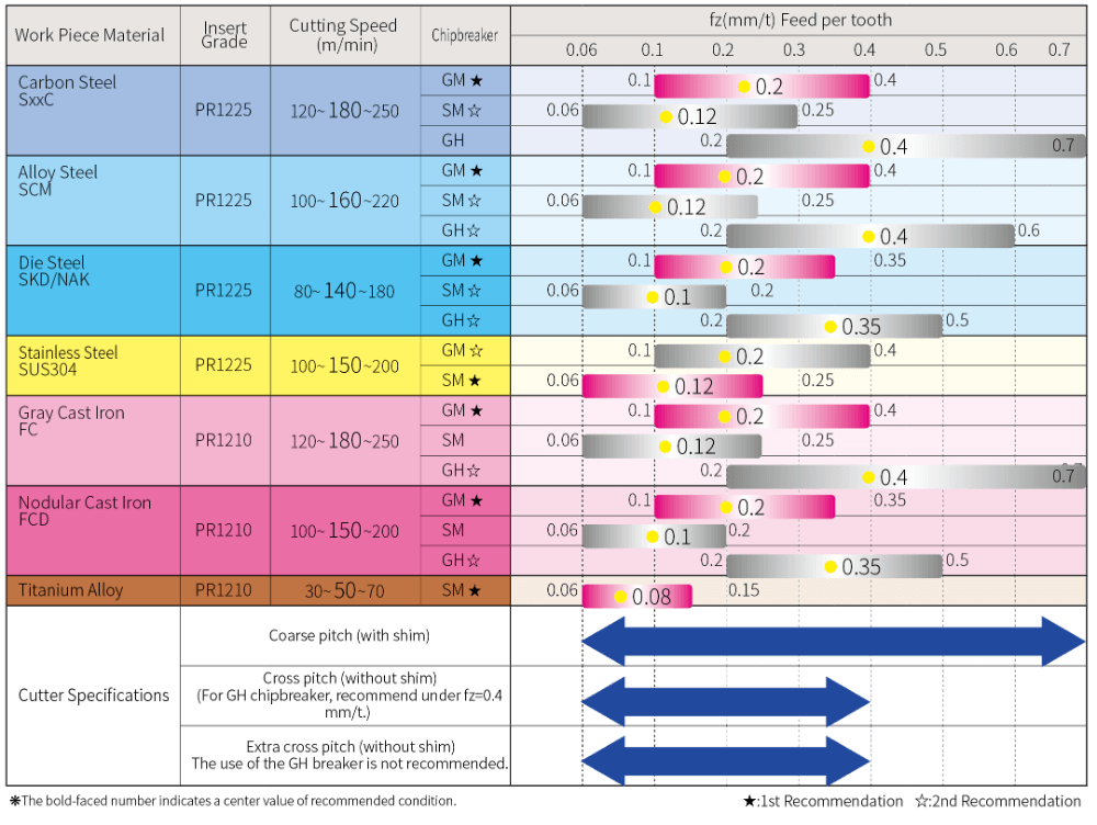
    Recommended conditions

    未命名 2 26 resized

檔案下載

Scroll to Top